|
|
|
|
||||
NIFS optics were installed in the NIFS cryostat in September 2002 in preparation for the second cool down. The optics and engineering detector will be used for the first time in NIFS in this cool down.
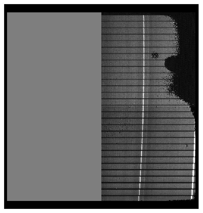
The following pictures show the first images of the reformatted "staircase" slit of the IFU on the field mirror array. The triple slit pattern at the central slitlet is due to light reflected from the unfanned anvils of the image slicer stack. These will eventually be baffled, but for now they provide a useful fiducial.
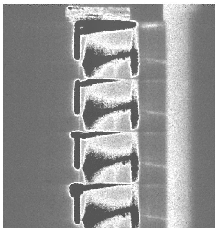
These pictures were taken with the pupil amd field mirror arrays in their nominal positions (with no adjustment). The enlarged field mirror image at right shows that a small gap exists between each slitlet image. This is due to a manufacturing error in the field mirror array. This array will be replaced in a subsequent cool down.
 Full staircase slit image on the field mirror array. |
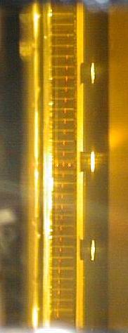 Field mirror array with staircase slit. |
 Enlargement of central region of staircase slit. The triple image marks the central slitlet. |
 Na I D doublet, J grating, II order warm with MUX. |
 Undispersd slit image using grating mirror. |
 Undispersd image of the pinhole array. |
 Undispersd image of the horizontal slit. |
The second cool down of the NIFS cryostat began on Monday 28-OCT-02. It was sufficiently cold to begin measurements by Thursday 31-OCT-02. Temperatures had stabilized by Monday 04-NOV-02.
The cryostat contains all of the NIFS spectrograph and OIWFS optics. The spectrograph occulting disks and Ronchi calibration mask are not installed. The J filter is not installed so that internal optical lamps can be viewed through the cryostat window. The camera lenses and collimator corrector lens have not been anti-reflection coated. The spectrograph detector is the first engineering detector that has only two working quadrants. This device dissipates excessive heat during operation. The OIWFS detector is not installed, and so the OIWFS filter/aperture wheel was not installed.
The spectrograph is giving excellent initial results. The IFU pattern occupies 2030 pixels in the spatial (vertical) direction, as expected. The pattern is displaced by 0.34 mm on the detector so there is a gap of 28 pixels (H grating) at the top instead of 9 pixels. This causes some of the bottom spectrum to be lost. The spectra are accurately aligned with detector rows, as is required. The spectra are also in reasonable focus with the spectrograph camera set to a nominal position. One purpose of this cool down is to determine the exact camera focus.
The images below show spectra of an incandescent flat field lamp and a Xenon arc lamp obtained with the Z, J, H, and K gratings. These are raw data with no data reduction. The flat field shows a modulation that appears to be due to the expected fringing in the sapphire layer of the detector. The H and K flats have average fringe periods of 14.5 and 17.9 pixels. The predicted fringe periods were 12.9 and 18.8 pixels. The arc lamp spectra show the expected staircase slit pattern. The strict staircase of the IFU combines with the curvature of a long slit spectrograph to reduce the upper slitlet displacements and accentuate the lower slitlet displacements. Multiplexer glow is apparent at various places in the arc lamp image.
The images below show the same set of flat field and arc lamp frames after dark frame subtraction.
Xenon arc lines at the top of the detector appear double while those at the bottom appear single. These are shown for the H grating below, but the effect is general. The Gaussian FWHM of the arc lines is ~ 7-8 pixels, except for slitlet 29 (the bottom one) that is significantly better at ~5-6 pixels. This may indicate that one of the camera lenses has cracked!. The narrower lines in slitlet 29 do not have greater peak intensities, so it is not simply that the light is more concentrated.
Undispersed images of the "staircase" pattern have FWHM of ~ 4 pixels. This may indicate that the gratings are not flat (?) or that the collimator is out of focus and producing astigmatism at the grating.
 1.6053 micron line in slitlet 5 of the H grating. |
 1.6053 micron line in slitlet 28 of the H grating. |
The 0.1 arcsec wide horizontal slit has been used to record dispersed images with one simulated "star" at the center of each slitlet (see below). The "star" images generally have FWHMs in the spatial (i.e., vertical) direction of 5-6 pixels. This is narrower than the spectral resolution achieved in all but the bottom slitlet. There is no indication of double images in the spatial direction for any slitlet.
 Dark-subtracted dispersed image through the 0.1 arcsec wide slit with the K grating. |
The result of subtracting a 15 s dark frame from a 30 s dark frame is shown below (left frame). This shows that the multiplexer glow continues throughout the integration, rather than just occurring during the readout. This has been removed (right frame) by 1) bias subtracting a 5.4 s bias frame from the 15 s dark frame, 2) bias subtracting a 5.4 s bias frame from the 30 s dark frame, and 3) dark subtracting the bias-subtracted 15 s dark frame from the bias-subtracted 30 s dark frame. The dark frame is scaled by 2.56 in this process to allow for the different exposure times.
 30 s dark - 15 s dark. |
 30 s dark - scaled 15 s dark. |
The image slicer has been imaged through the cryostat window with illumination from an internal incandescent lamp. The spot projector optics and a small CCD camera were used to record the images. It is possible to establish where the image slicer is in focus by moving the camera and optics axially. The pinhole array in the focal plane mask wheel was then rotated into the beam and its image recorded. This confirms that the focal plane mask wheel and image slicer are parfocal. A sequence of images is shown below.
The focal plane mask wheel aperture has been aligned to the image slicer by rotating the wheel and identifying the wheel positions that block half of the IFU slitlet length. This occurs approximately at focal plane mask wheel positions of 211700 and 214950 (see below), so the centered position is at approximately 213325.
 Focal plane mask wheel at 214950. |
 Focal plane mask wheel at 211700. |
The field mirror alignment has been checked by recording the undispersed "staircase" image alone and then with an internal lamp first illuminating the field mirror array and then illuminating the image slicer. These produce superposed images of the field mirror outline and the location of the "staircase" image on the field mirror array. In the first case, only the image slicer mirror associated with a particular field mirror is visible. In the second case, a diffusely illuminated image of the full image slicer is seen in every field mirror. The images of the top few slitlets are shown below. These demonstrate that the illumination is well centered on the field mirror array. The field mirror width is expected to be imaged to 167 pixels at the detector. This is difficult to discern in these images.
 External lamp only. |
 External + field mirror illumination. |
 External + image slicer illumination. |
The spectrograph grating pupil has been imaged through the cryostat window at four orthogonal orientations using the cold stop camera (see below). The outer extent of the pupil image is defined by the cold stop. The central shading is the diffracted image of a 10 mm diameter blackened disk on the grating diffuser. This confirms that the grating pupil has remained in good alignment with respect to the spectrograph cold stop during cool down.
 Grating pupil imaged with cold stop camera. |
Flexure tests have been performed by externally illuminating the 0.1 arcsec diameter pinhole in the focal plane mask wheel at recording the centroid of its image on the detector for different orientations of the NIFS cryostat. The pinhole centroid flops by ~ 0.5 pixels at a particular orientation. Defocussed images of the pinhole on either side of this flop orientation are shown below. These show that the centroid shift is due to a redistribution of light within the defocussed image, rather than a bulk translation of the image. This suggests that flexure will be very small once the spectrograph camera has been properly focussed.
 Pinhole image at 0 deg orientation about the cryostat window axis. |
 Pinhole image at 135 deg orientation about the cryostat window axis. |